Another six months has passed and I’m still not that much further along with the LEO-1. In the summer I started building the control board and tested a small section of it with good results. The oscillator, counter and first decoder plus some logic gates successfully generated some of the more important control signals. It’s a sad fact that it took a huge amount of time to get that section of the control board hooked up, and that only accounts for about a quarter of the whole board. Building the LEO-1 was starting to get seriously tedious.

Control board generating its first signals
At this point I chanced upon a distraction. I saw on eBay a 32 x 16 flip-dot display which was amazingly cheap, and always having wanted to play with one, I decided to buy it. This kept me busy from August until October while I built a really cool clock out of it. I had to reverse engineer it, figure out how it worked, and then design my own micro-controller and driver boards to make it work. And I had to write the software. It’s not finished yet, but it tells the time. It automatically sets itself from a GPS module too so it doesn’t even need any buttons.

Flip-dot clock
So, once again, LEO-1 took the back stage while I did something less tedious. But something happened while I was building the clock that changed my mind about the way I was building the LEO-1. For the first time, I actually had professional quality printed-circuit boards made. I used Express PCB which has reasonable pricing for small boards as long as you don’t bother with the silk screen and solder mask. When they arrived I was so impressed with the quality and speed of assembly that I started thinking about using them for LEO-1 as well.

PCB on flip-dot display
Now, earlier in this blog I had sadly stated that it would be too expensive to build the LEO-1 with PCBs, because the boards would have to be very large. If I hadn’t thought so I would have gone for it straight away and never looked back. But somehow I had convinced myself that I couldn’t justify spending large amounts of money on just the PCBs. What I didn’t realize was that instead, I was going to spend large amounts of time soldering individual wires, far more than the amount of time I would have to work to pay for PCBs. Besides, if I don’t accelerate the process I’ll never finish the blasted thing. So I did an experiment — I decided to build one of the LEO-1 boards in the PCB designer and see how it came out.
I chose the register board as it’s very repetitive. I then proceeded to spend two weeks working on it until I had painted myself into a corner and couldn’t place the last few traces. I had been so fixated on the register chips that I had forgotten to leave room for the traces to the LED drivers. This is what it looked like when I decided I was screwed:

Register board FAIL
I started again from scratch and spent another three weeks doing it right. When I wasn’t working on it, I was dreaming about it. I literally had dreams that involved trying to find efficient red and green routes from one place to another. I finally finished it yesterday. I had checked it and double-checked it constantly during the design process, but I was still unsure that it was correct. I checked it again. I printed it and checked it on paper, making sure everything would physically fit. I printed it to PDF and checked it at 800% zoom. This morning I finally decided to send it for manufacturing. As expected it’s quite big at 10.4″ by 13.3″. This is how it looks:
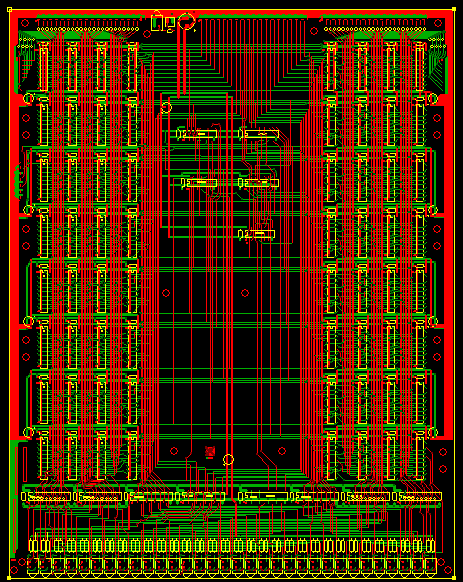
Register board
I’ve decided to keep the (almost finished) memory board as it is. I’m now working on the PCB design for the ALU and my experience with the register board has made it a lot easier to get it right. I’m already about half way through it. For a long time I couldn’t decide if I should keep working on the control board as it is, or ditch it and make a PCB for that too. I’m pretty sure that if the register board works out, I’ll do that. It’s annoying that I will have to desolder a bunch of stuff but at least I had the foresight to not solder all the pins of all the sockets and headers, just enough to keep them from falling out. It’s almost as if I knew…
Of course, I now have this nagging voice in my head telling me that I’m cheating. There I was, all set to build a CPU with my bare hands, but now I’m taking the easy way out. I just want to get it working so I can program it. Did the mainframe designers of the 1970s think they were cheating when they starting making their CPUs with PCBs instead of wire-wrapping? Hell no, they had simply found a way to save time. That’s how I’m justifying it to myself. I’m just saving time 😎

I’m happy to see that you don’t give up with this project.
In term of method complexity for building a complex board, I think that
* wire soldering is the most complex
* wrapping is easier, and faster.
* PCB etching is the easiest method, especially if you just design it and if you don’t manufacture it.
About the register board, I’m impressed: 70 components just for the register file, that’s huge.
3 internal tri-states busses, and 8x16bits registers, that’s a big challenge.
Why have you chosen a so complex architecture? Do you have an estimation of the total chip count of your computer? 300 or 400 components?
On my side, I have almost finished my CPU and computer project on an FPGA. The biggest part of this project was the software part, not the hardware part. I will write a website within a few weeks or months about it. I will keep you informed.
Thanks for sharing your project.
F4HDK – French hobbyist
LikeLike
Thanks for your encouraging comments. I know, I’m crazy! I often ask myself why I chose such a complex architecture 🙂 At first, I designed it in a simulator where buses were hidden behind one ‘wire’ and the registers were so simple. It’s only when you expand each bus to its 16 bits that it gets insane. The main reason for the 3-bus design was that it seemed very elegant, having eight registers that are all identical and can be used in any combination, and the way the instruction addresses them directly. You can use three registers in one instruction without needing microcode — e.g., mov r0, (r1+r2) happens in one instruction cycle (8 clocks).
I know the register board is overkill and I probably could have implemented it more easily using a ‘register file’ chip or something, but I just wanted to do it really old-school using individual chips. I learned a lot doing it this way too.
The entire design requires 284 ICs.
If you think the registers are complicated, wait until you see the ALU. I probably could have used some 74181s — but didn’t 😉
I look forward to reading your web page. Please let me know when it’s ready.
John
LikeLike
Hello.
My CPU project is now finished, and I have put all the documentation on the hackaday website :
https://hackaday.io/project/18206-a2z-computer
Do not hesitate to give me feedback about it.
LikeLike
Thanks for the link. I’ll have a good look and let you know what I think!
LikeLike
Good luck with your custom CPU. I agree PCBs are the best way to go – lots of smaller PCBs on a shared backplane. I used wire-wrapping for the BMOW1 computer, but only because I was ignorant of other methods when I designed it. Seeed or DirtyPCBs are better options than ExpressPCB, and you’ll get soldermask and silkscreen with them. Seeed is currently just $4.90 for 10 PCBs.
If you get stuck while routing complex boards, try starting with a physically larger board to give yourself a better ratio of empty space to ICs. You can also route it partly by hand, and partly with a tool like FreeRouting. FreeRouting saved my butt a couple of times on difficult PCBs I couldn’t manage to finish routing manually.
LikeLike
Hi Steve, thanks for your interest in my project. Along with Magic-1, BMOW was one of the first projects that originally inspired me to start this whole thing. Thanks for the advice. I can’t believe those Seeed prices! I originally investigated building it with lots of small boards on a backplane, but then I started building it on large breadboards instead. When that became too difficult, I switched from large breadboards to large PCBs because I wanted to keep the rows of LEDs on each level.
LikeLike